While completing some brake system repairs on the Mustang, I stumbled upon a characteristic of the factory braking system that rendered the vehicle in-op if done improperly.
 |
| 1969 Mustang with the 1987 4Runner |
This pertains to classic Mustangs with factory disc/drum and accompanying proportion valve and distribution block assembly.
 |
| '68-69 Factory Proportioning Valve and Distribution Block. Source: West Coast Classic Cougars |
The issue - While bleeding the brakes on your Mustang, your 'brake warning light' came on, or you may have lost fluid pressure entirely at one wheel.
The details - While bleeding mine, I made it through bleeding both rear drums and front-passenger caliper, but when I went to bleed the front-driver caliper, I got a huge puff of air, and then nothing. No fluid would come out. It wouldn't come out the bleeder, the soft line, it wouldn't even come out of the distribution block it's self when I removed the hardline. What. In. The. World. The 'brake warning light' had come on, and the Mustang couldn't stop straight to save it's self. The rear-passenger drum was locking up, the front-driver caliper was in-operative, and the front-passenger caliper was dragging. An absolute mess, and not safe to drive. Not knowing what the issue was, I threw new calipers at it, adjusted the drums, bled the system until I was blue in the face, but that won't fix it because...
The details - While bleeding mine, I made it through bleeding both rear drums and front-passenger caliper, but when I went to bleed the front-driver caliper, I got a huge puff of air, and then nothing. No fluid would come out. It wouldn't come out the bleeder, the soft line, it wouldn't even come out of the distribution block it's self when I removed the hardline. What. In. The. World. The 'brake warning light' had come on, and the Mustang couldn't stop straight to save it's self. The rear-passenger drum was locking up, the front-driver caliper was in-operative, and the front-passenger caliper was dragging. An absolute mess, and not safe to drive. Not knowing what the issue was, I threw new calipers at it, adjusted the drums, bled the system until I was blue in the face, but that won't fix it because...
The factory disc/drum system - Your factory distribution block has a brass piston internally. This piston free-floats in the distribution block housing, and controls primarily your 'brake warning light.' When your system develops a leak, the pressure changes drastically inside the distribution block, causing the piston to move and depress the 'brake warning switch.'
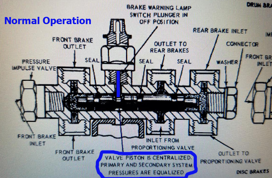 |
| Source: Ford Shop Manual. Inlet and Outlet labeling doesn't apply |
This piston also has 3 small o-rings and assists in routing brake fluid to the appropriate lines. When a leak is detected, and the piston moves due to pressure changes, the o-rings and their fluid directing properties move too. In my case, that second caliper jarred the internal piston loose and caused it to move 'forward' (towards the 'left front brake' line) and cut off fluid flow to the driver-front caliper. This piston isn't designed to stop or block a leak, it just happened to work out that way given the position of the unseated piston in relation to the brake line outlet. It also allowed for there to be no o-ring seal between the 'master cyl front bowl (rear brakes)', the proportioning valve inlet/outlet, and the rear brake outlet, causing fluid to bypass the proportioning valve and lock up the rear brakes while starving the remaining front caliper of the fluid pressure it needed to function properly.
 |
| Source: Ford Shop Manual. Inlet and Outlet labeling doesn't apply |
Due to the sensitivity of the piston to pressure changes, you have likely, or will likely, trip your 'brake warning light' at some point as you bleed your brake system
'Brake Warning Light' is On - What next?
'Brake Warning Light' is On - What next?
If you have a fresh distribution block, or a piston that moves easily, you can try the Ford Shop Manual recommended way for resetting the 'brake warning light' switch.
- Turn the ignition to 'ACC' or 'ON' (your 'brake warning light' should illuminate)
- Loosen the outlet line opposite of the line that caused the light to come on. For example, my front caliper caused the piston to move forward, so I need to loosen my REAR outlet at the block to move the piston backwards
- Once the appropriate outlet has been loosened, press on the brake pedal to build pressure in the distribution block, allowing the system to simulate a 'leak' and move the piston.
- Once the piston moves enough to turn off the 'brake warning switch', tighten all lines and top off the reservoir.
You can do the above steps delicately, or give it a good 'panic stop' stomp. Neither way worked for me.
When the Shop Manual Recommended way doesn't work - What next?
When the Shop Manual Recommended way doesn't work - What next?
When your distribution block piston refuses to move under reasonable circumstance, it's time to remove and dissemble.
I would recommend getting a distribution block rebuild kit and SST handy for this next part. Even if you have a brand new exact replica distribution block, you don't know what you're going to find in there.
Start by draining and removing your master cylinder
 |
| Master cylinder and brake switch removed |
Loosen 'Right Front', 'Left Front' and 'Rear' brake lines - Leaving the master cylinder lines and proportioning valve lines tight.
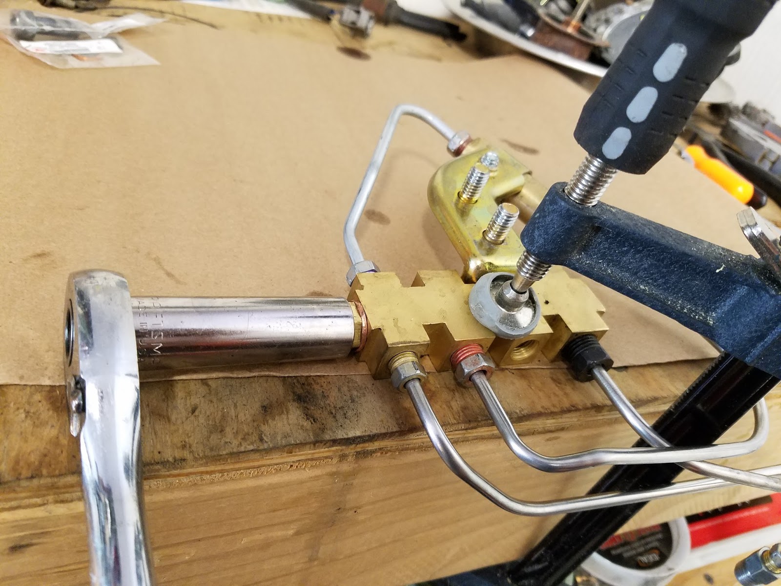
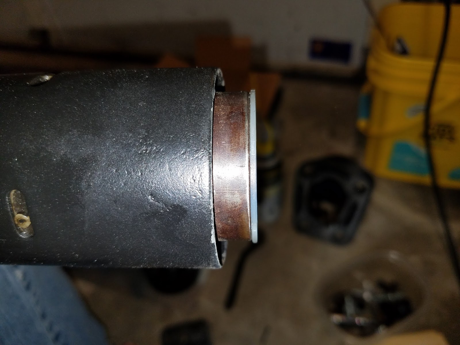
To remove the internal piston, loosen and remove the bolt and copper crush sleeve on the rear of the distribution block.
 |
| Location of access bolt and copper crush sleeve on rear of distribution block |
 |
| Protect the brass body and brake lines, if extra force is needed. You may need to tap the socket while ratcheting, to break the bolt loose. |
 |
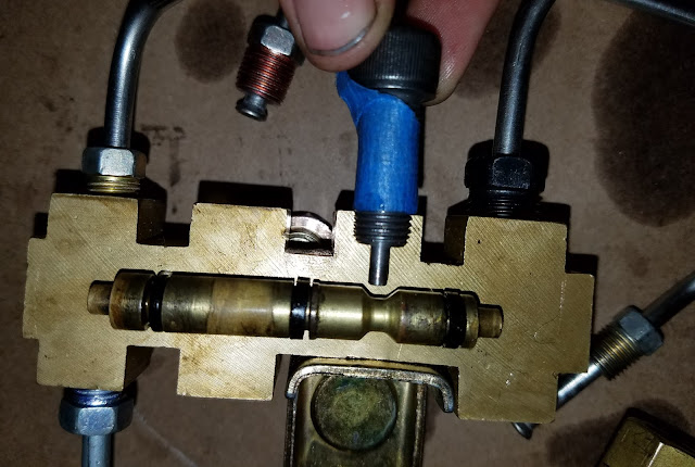
| Use a small punch to push the piston out through the access port by poking it from the 'Left Front' brake port. |
 |
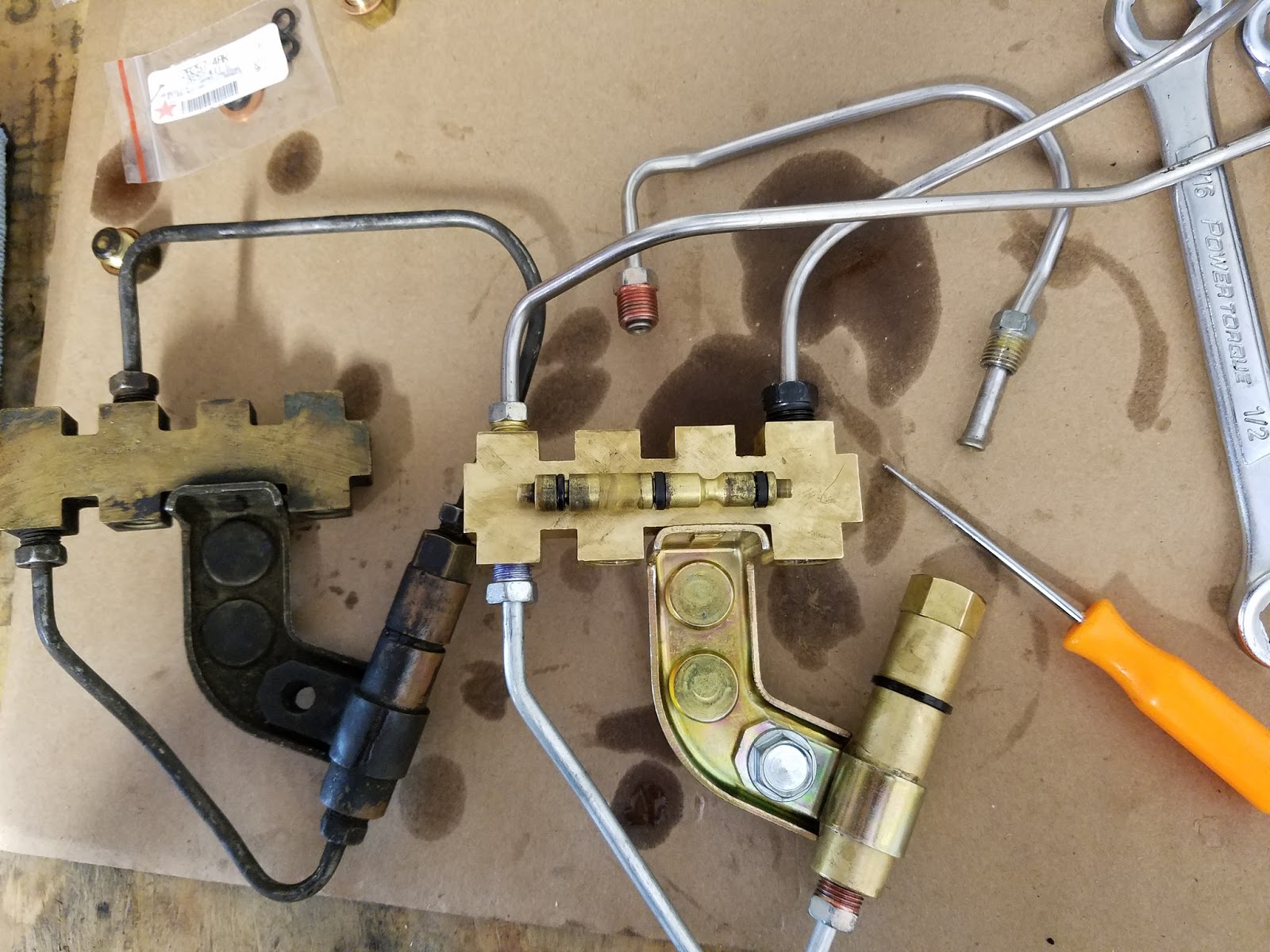
| Factory piston on the left, NPD rebuilt piston on the right |
 |
| Misplaced o-rings during rebuild may be what caused this piston to seize. Note the flat rings and the (1) round o-ring. The round o-ring should be on the 'rear' end, closest to the rear brake lines. |
 |
| New o-rings installed and SST fitted. Give a gentle push on the piston once the SST is installed to make sure the SST is fully seated and will hold the piston in place |
 |
| Piston installed, access bolt tighten, SST installed. Ready to install in the vehicle and bleed |
What if you haven't touched your brake system yet, and want to do it right the first time?
Here is how I would do it, given the chance to do it again and do it right from the beginning.
- Order all your parts and get them ready. My system was rotted out, and needed the Midland booster, master cylinder, master cylinder adapters, complete hardline kit (stainless), brake line retainer clips, factory distribution block/proportioning valve, braided stainless soft lines, rear softline-to-hardline adapter, and the calipers I thought would fix the problem
- Get your tools ready. I recommend the Baer Push Rod Length Gauge, the Mustang Brake Pressure Differential Switch Lock tool (Factory SST), and the piston rebuild kit for your distribution block. I got mine from NPD
- Clean and paint your pot metal pieces (calipers, drums, master cylinder). It all looks great and clean now, but it'll turn a lovely fuzzy shade of rust without some paint
- Start from the rear and start installing from the rear forward. If you jump around, you're likely to miss something
- When installing your distribution block, use the SST from the beginning. The piston is very sensitive to pressure changes and will likely knock it's self out of place if left free-floating
- Measure your brake booster push rod length against your master cylinder using the Baer gauge and adjust until there is 5lbs of pressure between the rod and master cylinder seat (per the Ford Shop Manual). Contact, but no master cylinder movement at rest, is ideal
- Bench bleed the master cylinder and install
- Pump up the system to build pressure
- Check all the new fittings with a fresh paper towel for leaks or weeping
- If leaking, stainless lines need to be tightened, backed off, and tightened again to seat properly due to the stiffer material
- Bleed the system with a buddy when the system is tight and dry
Hopefully this saves you some headache when servicing your own classic Mustang brake system!


