The list of parts I used to rebuild my steering column assembly isn't representative of all the parts available, but these are the parts most likely to wear out or break.
- Steering Shaft Insulator (3E629)
- Transmission Selector Tube Seal (7C102)
- Lower Steering Column Tube Bearing (7347)
- Tube Plug (3B361) - Comes with 3E629 above
 |
| Part Numbers and Illustrations apply Source: Online Review |
 |
| Descriptions and Various Parts apply Source: Haynes Manual |
 |
| Descriptions. Illustrations, and Part Numbers apply Source: 1969 Ford Car Shop Manual |
 |
| Source: 1969 Ford Car Shop Manual |
Disassembly
1.) Disconnect the battery
2.) Disconnect the Turn Indicator Switch wiring harness (under dash)
3.) Remove steering wheel (process will vary slightly if original or after-market)
4.) Remove Turn Signal Switch Lever
5.) In the engine bay, remove the rag joint from the steering box input shaft (7/16" Universal Socket)
6.) Under the dash at the firewall, disconnect the firewall bracket and seal (3513)
7.) Disconnect and remove steering tube assembly bracket from the dash
The steering column assembly will now be loose and can be pulled through the firewall, including attached rag joint.
Disassembly Continued
8.) Disconnect and remove rag joint from steering shaft flange
9.) Disconnect and remove turn signal indicator switch and hazard grommet
10.) Remove Steering Shaft C-Clip (3C610) and remove spacer, bearing, and bearing sleeve. The steering shaft is now free and pulls out of the bottom of the assembly
 |
| Bearing Retaining C-Clip (3C610), Spacer, Bearing (3517), and rubber Bearing Sleeve (3518) |
11.) Disconnect Shift Tube Retaining Bolts. The bolts will fall down into the upper steering shroud, which is fine.
 |
| Shift Tube Retaining Bolts. The initial view of them underneath the turn signal indicator switch |
12.) Disconnect Phillips head screws and remove the upper shroud. You can retrieve the shift tube retainer bolts and fully remove the turn signal indicator switch now. Shift Tube and Steering Column Tube are now free and pull a part from each other.
 |
| Phillips head screws for the upper shroud |
13.) Take note of bearings (plastic) and spacers (foam) still intact in Shift Tube and Steering Column Tube
 |
| Steering Column Tube and Shift Tube. Note the plastic bearing (upper 7347) that is not available as a reproduction |
 |
| Reproductions and salvaged parts ready for install |
Reassembly
After cleaning, prepping, and painting the assembly, you're ready to put it back together.
1.) Insert the salvaged 7347 upper bearing into the steering column tube, making sure the tabs face upwards, towards the top of the tube, and the retaining dimples line up with the cut-outs on the steering column tube
 |
| Upper 7347 bearing inserted into steering column shift tube |
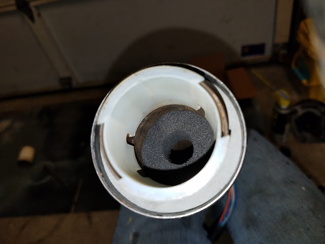
2.) Install foam seal 7C102 into steering column tube and push it in until it rests against the bottom of 7347
 |
| 7C102 seal installed into steering column tube |
3.) Install foam seal 3E629 into the shift tube, and push it down into the tube by about an inch
4.) Install plastic bearing 7347 (lower, reproduction available) into the end of the shift tube
5.) Install shift tube into steering column tube, rotating slightly so as to work it past foam seal 7C102
 |
| Foam seal 3E629 and plastic bearing 7347 (lower) installed into shift tube. Shift tube then installed into steering column tube |
 |
| Underside of the upper shroud, with retaining bolts very loosely threaded on |
7.) Run the turn signal indicator switch wiring through the upper shroud hole
8.) Align your steering column tube, shift tube, and lower shroud so that the bolt on the underside of the column is accessible (it's about to all come together)
 |
| Steering column tube, shift tube, and lower shroud all aligned so that bolt on underside of column is accessible |
9.) Run the turn signal indicator harness through the bottom shroud
 |
| Upper shroud and lower shroud harness recesses are offset by roughly 10-degrees |
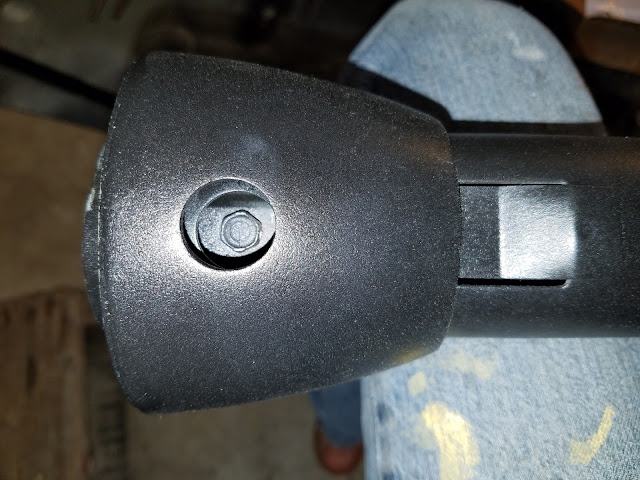
11.) Press upper shroud onto steering assembly, making sure retaining bolts are loose enough to swing out of the way, and come back to rest in shift tube retainer cut-outs. Tighten retainer bolts and Phillips head screws
Your shift tube is now connected to the steering column tube, and your upper shroud to the steering assembly. The shift tube will stick out by roughly half an inch from the bottom of the steering column tube and should feel solidly attached. If not, loosen retainer bolts and reseat them.
 |
| Shift Tube Retaining Bolt cut-outs on Shift Tube |
12.) Install firewall seal (3513) and firewall bracket onto steering shaft. These do fit over the steering shaft flange, but it is very snug
13.) Install steering shaft into shift tube/steering assembly
 |
| Firewall seal and firewall bracket installed. They do fit over the flange, but it's tight |
14.) Install bearing sleeve (3518), bearing (3517), spacer, and bearing retainer clip (3C610-B). I greased my bearing with marine grease, but greasing it at all isn't necessary
 |
| Bearing sleeve, bearing, spacer, and c-clip installed. Your c-clip may rest where the screwdriver indicates. I installed mine further down on the steering shaft to sit closer to the spacer |
15.) Fasten turn signal indicator, hazard grommet, and steering adapter to upper shroud (if using aftermarket steering wheel).
 |
| Column is ready for install into the Mustang. Note: Don't install the rag joint on the shaft yet |
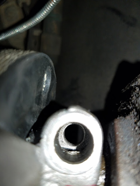
16.) At the steering box input shaft, install the keyed rag joint. To help align the rag joint, mark the flat tooth on the outside of the rag joint with Sharpie
 |
| Keyed rag joint, aligned and ready to be seated |
 |
| When seating the rag joint, align the bolt recess (about 1/4" between steering box and rag joint). Otherwise the bolt won't thread in |
 |
| Bolt recess aligned and ready to be tightened |
17.) Take the steering column assembly and insert it through the firewall. Loosely install the dash bracket (to hold the column at the correct angle)
18.) Install foam plug 3B361 into the end of your steering shaft. Align and mate the steering shaft to the rag joint and tighten rag joint bolts
19.) Tighten dash bracket bolts
20.) Install and tighten firewall bracket bolts
21.) Straighten wheels and install steering wheel
22.) Install turn signal indicator lever
23.) Install horn
24.) Install turn signal indicator harness (under dash)
25.) Reconnect battery
26.) Start engine. With vehicle in park, turn wheels fully left and fully right, and test turn signal indicators
Thanks for reading!
Disclaimer #1: My dash bracket hardware had been changed out long ago, requiring me to remove my dash to reach the hardware. This isn't typical, but it's a possibility for any Mustang.
Disclaimer #2: This write-up is purely from memory. If I missed something, please put it below in the comments, along with where it should go in the process, and I'll update it to reflect your addition.


