Friday, December 9, 2016

Rebuilding 1969 Mustang Non-Tilt ('Telescoping') Steering Column

Rebuilding the Non-Tilt ('Telescoping' or 'Collapsing') steering column on your 1969 Mustang isn't particularly difficult, but the information explaining 'how-to' is few and far between. In this write-up, I will list the parts available and where to find them, share exploded views from multiple sources, and explain how I rebuilt my steering column assembly.

The list of parts I used to rebuild my steering column assembly isn't representative of all the parts available, but these are the parts most likely to wear out or break.

Part Numbers and Illustrations apply
Source: Online Review 

Descriptions and Various Parts apply
Source: Haynes Manual

Descriptions. Illustrations, and Part Numbers apply
Source: 1969 Ford Car Shop Manual
Before we begin disassembly, it's important to understand why our steering shaft may need a rebuild. One reason is that the bearings and seals are made of plastic and foam which deteriorate over time, causing slop in the shaft it's self. Another reason is that the steering column is designed to collapse on impact, sacrificing the internals of the steering column tube to minimize damage to the driver.  If your column has collapsed due to impact, a replacement steering shaft assembly is recommended. 

Source: 1969 Ford Car Shop Manual
When I began my steering column rebuild, I did not expect I would be needing to write-up the process. After seeing the lack of information available on reassembly, I decided one was needed. Because of this oversight, I did not document the tear-down process, but will list the general steps to get you started.

Disassembly

1.) Disconnect the battery
2.) Disconnect the Turn Indicator Switch wiring harness (under dash)
3.) Remove steering wheel (process will vary slightly if original or after-market)
4.) Remove Turn Signal Switch Lever
5.) In the engine bay, remove the rag joint from the steering box input shaft (7/16" Universal Socket)
6.) Under the dash at the firewall, disconnect the firewall bracket and seal (3513)
7.) Disconnect and remove steering tube assembly bracket from the dash

The steering column assembly will now be loose and can be pulled through the firewall, including attached rag joint.

Disassembly Continued

8.) Disconnect and remove rag joint from steering shaft flange
9.) Disconnect and remove turn signal indicator switch and hazard grommet
10.) Remove Steering Shaft C-Clip (3C610) and remove spacer, bearing, and bearing sleeve. The steering shaft is now free and pulls out of the bottom of the assembly

Bearing Retaining C-Clip (3C610), Spacer, Bearing (3517), and rubber Bearing Sleeve (3518)
11.) Disconnect Shift Tube Retaining Bolts. The bolts will fall down into the upper steering shroud, which is fine.

Shift Tube Retaining Bolts. The initial view of them underneath the turn signal indicator switch

12.) Disconnect Phillips head screws and remove the upper shroud. You can retrieve the shift tube retainer bolts and fully remove the turn signal indicator switch now. Shift Tube and Steering Column Tube are now free and pull a part from each other.
Phillips head screws for the upper shroud

13.) Take note of bearings (plastic) and spacers (foam) still intact in Shift Tube and Steering Column Tube

Steering Column Tube and Shift Tube. Note the plastic bearing (upper 7347) that is not available as a reproduction

Reproductions and salvaged parts ready for install

Reassembly

After cleaning, prepping, and painting the assembly, you're ready to put it back together.

1.) Insert the salvaged 7347 upper bearing into the steering column tube, making sure the tabs face upwards, towards the top of the tube, and the retaining dimples line up with the cut-outs on the steering column tube

Upper 7347 bearing inserted into steering column shift tube

2.) Install foam seal 7C102 into steering column tube and push it in until it rests against the bottom of 7347

7C102 seal installed into steering column tube

3.) Install foam seal 3E629 into the shift tube, and push it down into the tube by about an inch
4.) Install plastic bearing 7347 (lower, reproduction available) into the end of the shift tube
5.) Install shift tube into steering column tube, rotating slightly so as to work it past foam seal 7C102

Foam seal 3E629 and plastic bearing 7347 (lower) installed into shift tube. Shift tube then installed into steering column tube
6.) Take the upper shroud and install your retaining bolts. Only thread the nut on by one thread, allowing the bolts to be floppy (very important later)

Underside of the upper shroud, with retaining bolts very loosely threaded on

7.) Run the turn signal indicator switch wiring through the upper shroud hole
8.) Align your steering column tube, shift tube, and lower shroud so that the bolt on the underside of the column is accessible (it's about to all come together)

Steering column tube, shift tube, and lower shroud all aligned so that bolt on underside of column is accessible

Use a socket to help keep steering column tube and shift tube aligned
9.) Run the turn signal indicator harness through the bottom shroud

Turn signal indicator harness runs through lower shroud, with socket holding alignment
Upper shroud and lower shroud harness recesses are offset by roughly 10-degrees
10.) Align upper shroud with steering assembly by lining up Phillips screw head seats, retainer bolt heads with shift tube cut-outs, and wiring harness recess
11.) Press upper shroud onto steering assembly, making sure retaining bolts are loose enough to swing out of the way, and come back to rest in shift tube retainer cut-outs. Tighten retainer bolts and Phillips head screws

Your shift tube is now connected to the steering column tube, and your upper shroud to the steering assembly. The shift tube will stick out by roughly half an inch from the bottom of the steering column tube and should feel solidly attached. If not, loosen retainer bolts and reseat them.

Shift Tube Retaining Bolt cut-outs on Shift Tube

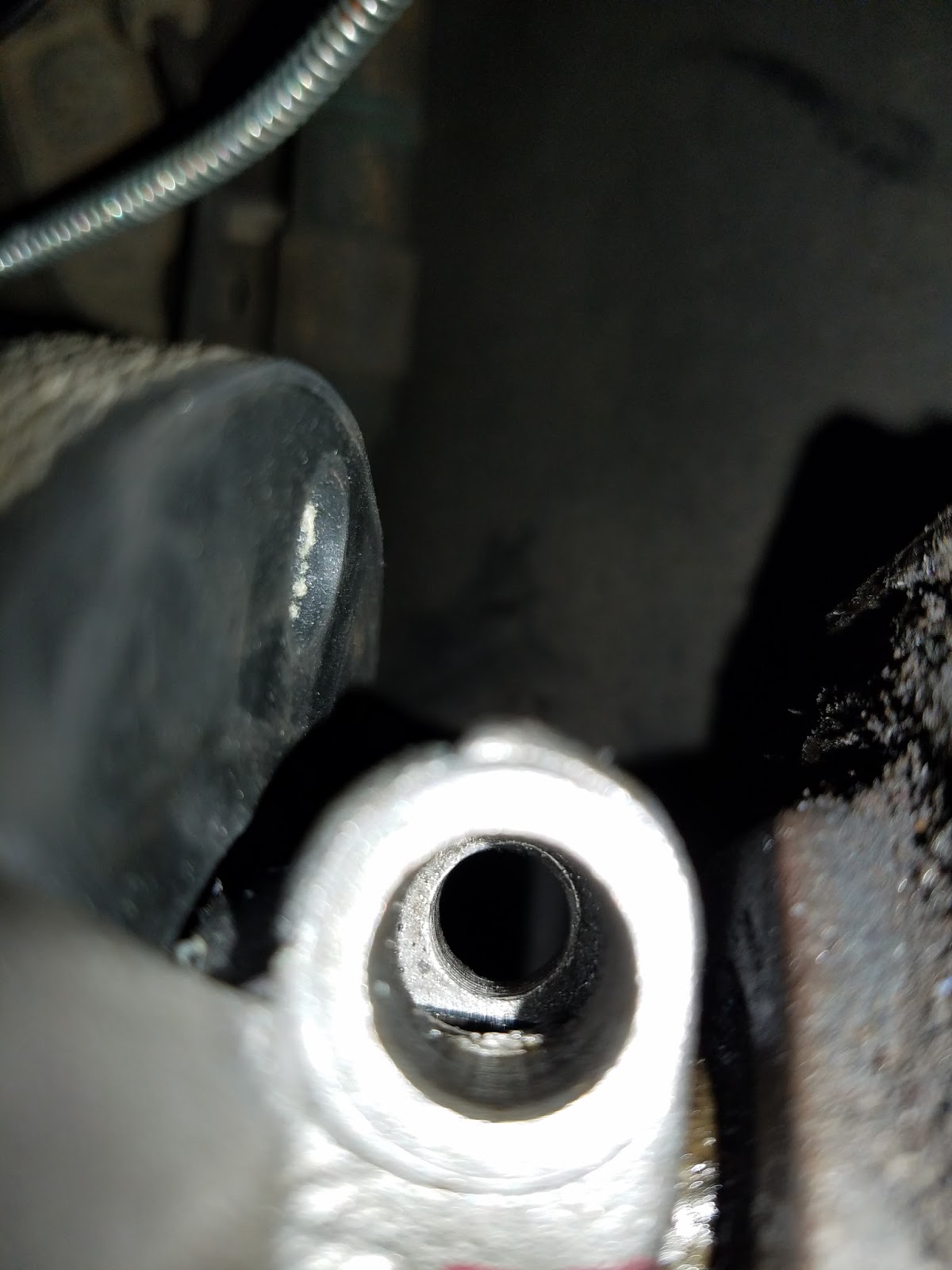
Shift Tube protruding from bottom of Steering Column Tube when installed
12.) Install firewall seal (3513) and firewall bracket onto steering shaft. These do fit over the steering shaft flange, but it is very snug
13.) Install steering shaft into shift tube/steering assembly

Firewall seal and firewall bracket installed. They do fit over the flange, but it's tight

14.) Install bearing sleeve (3518), bearing (3517), spacer, and bearing retainer clip (3C610-B). I greased my bearing with marine grease, but greasing it at all isn't necessary

Bearing sleeve, bearing, spacer, and c-clip installed. Your c-clip may rest where the screwdriver indicates. I installed mine further down on the steering shaft to sit closer to the spacer

15.) Fasten turn signal indicator, hazard grommet, and steering adapter to upper shroud (if using aftermarket steering wheel).

Column is ready for install into the Mustang. Note: Don't install the rag joint on the shaft yet

16.) At the steering box input shaft, install the keyed rag joint. To help align the rag joint, mark the flat tooth on the outside of the rag joint with Sharpie

Keyed rag joint, aligned and ready to be seated

When seating the rag joint, align the bolt recess (about 1/4" between steering box and rag joint). Otherwise the bolt won't thread in

Bolt recess aligned and ready to be tightened

17.) Take the steering column assembly and insert it through the firewall. Loosely install the dash bracket (to hold the column at the correct angle)
18.) Install foam plug 3B361 into the end of your steering shaft. Align and mate the steering shaft to the rag joint and tighten rag joint bolts
19.) Tighten dash bracket bolts
20.) Install and tighten firewall bracket bolts
21.) Straighten wheels and install steering wheel
22.) Install turn signal indicator lever
23.) Install horn
24.) Install turn signal indicator harness (under dash)
25.) Reconnect battery
26.) Start engine. With vehicle in park, turn wheels fully left and fully right, and test turn signal indicators


You should have a stout-feeling connection to the steering box now, and a great-looking steering column to show for your efforts.


Thanks for reading!


Disclaimer #1: My dash bracket hardware had been changed out long ago, requiring me to remove my dash to reach the hardware. This isn't typical, but it's a possibility for any Mustang.

Disclaimer #2: This write-up is purely from memory. If I missed something, please put it below in the comments, along with where it should go in the process, and I'll update it to reflect your addition.

Thursday, November 28, 2013

Repainting the 4Runner Fiberglass Shell: The $50 Paint Job Way

This is less of an instructional, and more of a "ehhh, it looks better than it did."

Using the $50 Paint Job as a rough guideline, I set out to make my 4Runner's fiberglass shell look better than this. Duct tape stains, chips, faded factory paint, she had it all.

Fiberglass shell before
2 Coats primed, with 300 grit inbetween
I opted to move the shell into the garage to protect from weather, and to reach the center of the roof better.

Start by sanding shell with 150 grit to knock down blatant imperfections. Wipe with damp (water) cloth, then hit with 300 grit. Wipe with mineral spirits and let dry.

Take a can of Rust-oleum filler primer and apply your first coat. 
Smooth as silk after primer and sanding


I sanded with 300 grit between primer coats, and lightly used 600 grit after my final primer coat. I applied 4 or 5 primer coats total to help fill in the trail scratches and chips. The primer will be very dusty, and I highly recommend a breathing mask. Ideally, remove dust from sanding with compressed air.
First coat of Rust-oleum Black Satin Enamel


For paint, I used Rust-oleum Satin Enamel in the can, with foam rollers, and foam brushes. The brushes are almost pointless, but get one or two for getting around the drip-guides of the fiberglass shell.

I cut my enamel 50/50 with mineral spirits. This is thicker than $50 Dollar Paint Job, but I found with thicker paint, I got less roller marks. 
Two coats paint, then wet sand


After two coats, I began sanding with wet sand paper. I used 600 grit, soaked 15-minutes in water, then sanded with a spray bottle of water to keep everything well-lubricated.

In the Texas heat, I was able to apply about 3 coats per day. Typically 2 coats will be the daily maximum.

Four coats paint, getting ready for 1000-1500 grit wet sand


I cleaned my paint with mineral spirits after sanding. Reading back, this is apparently unadvised, as it can eat the paint. I personally didn't notice a problem.

After 2 coats I used 600 grit, after 4 coats I used 1000, 5th coat I used 1500, 6th coat I used 2000 grit. I had the grand plan of polishing with compound, but it honestly looked good the way it was.
Six coats paint and 2000 grit wet sanded.


In retrospect, the satin finish was probably the best finish I could have picked. Flat eventually absorbs moisture, and gloss would have been very hard to work with and smooth out. I would 100% recommend satin for this model of 4Runner shell.


Then apply liberally with grit and mud 
On the plus side, the satin finish cleans up great with a pressure washer


Good info from the pros:

Wednesday, November 27, 2013

Cutting Toyota Fenders Without Welding

 This was preformed on a 1987 4Runner with extensive body damage. 
If you have a clean 4Runner, please consider more professional options first.

When I bought my 4Runner, it had already been laid down, beat out, and rust patched with fiberglass, expanding foam, and kitchen drawer slides. No joke. Not only was it ugly, but it also got in the way of the 4Runner's great articulation. For many reasons, that all needed to come out.

Rear fenders before modifications


Masking tape and Sharpie. I decided to cut an inch higher than pictured here.

A great way to start trimming fenders, is to lay out some masking tape on the fenders and use a Sharpie to draw where you want your cut. I made a very large cut because I wanted to remove all the rust and fiberglass. It is popular however to make a less pronounced cut, and to follow the factory body lines.


Following the Sharpie line, make your cut


Once you have decided where you want your fender lines, you're ready to cut. For the rear fenders, it is advisable to use a grinder with a cut-off wheel. I used a Sawzall with a new steel 4" blade however. If you decide to use a Sawzall too, make sure to angle the blade to avoid hitting the rear seatbelts and speakers, and tape all wires out of the way.


What you see here is the factory wheel tub hanging out much lower than our new fender line. This is usually where a welder comes in handy, but not for us. Details to follow.

Optional step
Great for mild weather, or if you don't mind "weather" in your fenders

This step is optional. I ran around with my fenders like this for a month while I decided how I wanted to patch the wheel tub. 

Take the Sawzall and make 4-6" cuts perpendicular to the fender in the wheel tub. Take a shop hammer and large channel lock pliers and bend/hammer the wheel tub strips up into the fender.  


Wheel tub pushed up into the fender and out of the way


This optional step will look close to this when you're finished. Minimize hitting the actual fender, and just aim the hammer at the wheel tub strips. The channel lock pliers will help in getting the "reverse bend" in the strips gracefully started.


Wheel tub removed to pinch weld
and steel bar supports riveted 


When you're ready to continue with the wheel well, remove the tire, and use the Sawzall to remove the wheel tub within 1-2" from the pinch weld. Masking tape won't stick here, but the pinch weld is visible enough from inside the wheel well.

For this next part, you'll need some steel rivets, a steel rivet gun (not aluminum), some steel bar from Home Depot/Lowes, and one of the 5' industrial carpet mats for $20 they carry in the flooring section.

Cut the steel bar into strips and bend the ends with a vice and large pliers. I ended up using my leaf springs and body weight to bend the steel after awhile. I don't advise this if you have nice leafs. Bend the steel so that it matches the curve of the fender. Drill holes into the fender for your rivets, then line the bar up, mark it with a Sharpie or drill, then remove and fully drill a hole through the steel bar. Rivet bar into place in fender. Rinse and repeat around the entire wheel well, making sure to place steel bar at corners and top of wheel well for support.


Steel bars installed and painted black


This is what the steel bars will look like when you're finished. It began raining before I could install the tub, so I sprayed them black to help protect against rust.


Creating a pattern. Area is roughly 1.5'x5'


Before you cut your rubber floor mat, create a pattern and factor in any tucks, folds, etc. you'll need in the material. Remember, measure twice, cut once.

Once you have a pattern you're happy with, lay it on the floor mat and cut the floor mat so that the carpet faces inside the fender, and the rubber backing faces outside, towards the tire. 


Flip your pattern so that rubber faces outside


If you reuse your pattern for the other wheel well, remember to flip it so that the carpet will still face the inside of the fender, and the rubber to the outside.


Bolting the fender rubber into place


Now you're ready to install the rubber into the wheel well.

I used 1/2" bolts with washers for strain relief on the rubber. Drill bolt holes one at a time into the steel strips and existing wheel well, and poke the bolts through the rubber using a small phillips-head screwdriver. Adjust rubber as needed after each bolt is installed to ensure the rubber lays flat.

Perimeter bolts installed, and rubber sliced to tuck into fender


Rubber tucked into fender, and black adhesive installed
After the bolts are installed, slice the rubber so that you can tuck it up into the fender. Use a fresh razor knife for best cuts, and go slow so you don't slice too far or too much.


Once you have your rubber tucked into the fender, take some black adhesive and caulk into and around the seams of where the rubber meets the fender. Smooth adhesive and re-apply once set up if you need to build up an area. 


Inside view of fender


While caulking with adhesive, access the inside of your fender from the bed of the 4Runner and push the extra rubber material against the inside of the fender. You should have ample adhesive here, and it will cause the rubber to adhere to the fender. This forms more support and a better seal between the rubber and fender.

If you push any adhesive out the fender, smooth it out with your finger while it's still wet.

Let adhesive fully set before painting


Repainting rear fenders to match lines of front fenders.
Dust bolts and seams with rattlecan bedliner to texture and blend
35" tires don't touch these fender tubs at all.